💡 Direct Answer & Executive Summary (Capacitance Electric Charge Solver)
Definition: Compute values for Capacitance Electric Charge Solver in standard SI units physics.
Governing Math Formula: Physical equation system model for Capacitance Electric Charge Solver.
Target Applications: Provides real-time quantitative solutions in Physics & Engineering for students, engineers, researchers, and finance professionals.
Capacitance & Electric Charge Solver ()
1. Introduction
From the microscopic decoupling capacitors stabilizing nanometer-scale logic voltage rails on multi-core computer CPU motherboards to the massive capacitor banks storing mega-joules of pulse power for nuclear fusion research lasers and electromagnetic railguns, capacitors are foundational components of modern electronic engineering.
Unlike chemical batteries—which rely on slow, temperature-sensitive chemical reduction-oxidation reactions to generate power—Capacitors store electrical energy electrostatically in the physical electric field () established between conductive plates separated by an insulating dielectric medium. This electrostatic mechanism enables capacitors to charge and discharge immense surges of power in fractions of a microsecond.
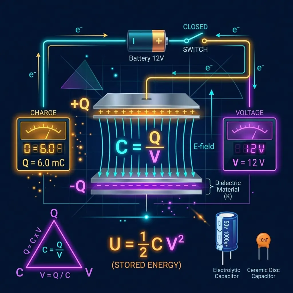
The fundamental physical capability of a system to store electrostatic charge per unit potential difference is defined as Capacitance ().
graph LR
    Q["⚡ Accumulated Charge (Q)
Electric Quantity in Coulombs (C)"] --> DIV["➗ Divided By"]
    V["🔋 Potential Difference (V)
Applied Voltage in Volts (V)"] --> DIV
    DIV --> C["⚡ Capacitance (C)
C = Q / V in Farads (F)"]
    C --> U["💡 Electrostatic Energy Stored
U = ½ · C · V² in Joules (J)"]
    C --> RC["⏱️ RC Circuit Time Constant
τ = R · C (Seconds)"]
Mastering capacitance calculations allows electronic designers, biomedical engineers, and physicists to:
- Design medical defibrillators that deliver precisely calibrated Joules of electrical countershock to restore normal heart rhythms during cardiac arrest.
- Engineer switched-mode power supplies (SMPS) with ripple filter capacitors that deliver clean, noise-free DC power to sensitive semiconductors.
- Model touchscreen capacitive sensing arrays that detect finger proximity via sub-picofarad capacitance changes.
- Calculate resonant tank tuning frequencies () for RF radio receivers, Wi-Fi transmitters, and radar antennas.
- Protect power distribution grids using power factor correction (PFC) capacitor banks that cancel out inductive motor phase lags.
2. Definitions & Analogies
2.1 The Simple Definition
In simple everyday terms:
- Voltage () is the electrical pressure trying to push electric charge onto a surface.
- Electric Charge () is the actual amount of electrons accumulated (measured in Coulombs, ).
- Capacitance () is the "storage capacity" or tank size of the electrical component (measured in Farads, ).
- If a capacitor has high capacitance, it can hold an immense amount of charge with only a small applied voltage ().
2.2 The Formal Technical Definition
Fundamental Definition of Capacitance
Formally, capacitance is the scalar ratio of the magnitude of electric charge () on either conductor plate to the potential difference () maintained between them:
- SI Base Unit: Farad () .
- Because one Farad is an extraordinarily vast amount of electrostatic storage, practical electronic engineering utilizes metric submultiples:- Microfarad (): .- Nanofarad (): .- Picofarad (): .
Parallel-Plate Geometric Capacitance Formula
For a parallel-plate capacitor with plate surface area () and separation distance () filled with an insulating dielectric of relative permittivity ($\kappa$ or ):
Where:
- is the Vacuum Permittivity Constant ().
- $\kappa$ () is the dimensionless Dielectric Constant of the insulating barrier.
- is the overlapping plate area ().
- is the plate separation gap ().
2.3 The Water Membrane Pressure Tank Analogy
To visualize capacitance intuitively, compare a capacitor to a sealed water tank divided by a flexible elastic rubber membrane:
graph TD
    subgraph Hydraulic_Model ["💧 Hydraulic Elastic Membrane Tank"]
        Pump["Water Pump Pressure (P)
(Water Pressure = Voltage V)"]
        Water["Trapped Water Volume (Q)
(Displaced Gallons = Charge Q)"]
        Flex["Elastic Membrane Flexibility (C)
(Stretchy Area = Capacitance C)"]
        Pump -->|"Pushes Water"| Water
        Water -->|"Stretches Rubber"| Flex
    end
    subgraph Electric_Model ["⚡ Electronic Capacitor"]
        Battery["DC Power Supply Voltage (V)
(Electric Potential in Volts)"]
        Electrons["Accumulated Electrons (Q)
(Charge in Coulombs)"]
        Dielectric["Dielectric Insulation Barrier (C)
(E-Field Polarization = Farads)"]
        Battery -->|"Forces Charge"| Electrons
        Electrons -->|"Polarizes Dielectric"| Dielectric
end- Water Cannot Cross the Barrier: Just as water cannot physically cross the solid rubber membrane, electrons cannot pass through the insulating dielectric barrier.
- Energy is Stored in Elastic Strain: Pumping water pushes against one side, ballooning the flexible membrane. The energy is stored in the elastic tension of the stretched rubber—just as energy in a capacitor is stored in the polarized electrostatic electric field () between the plates.
- Instant Discharge: If you release the valves, the stretched membrane snaps back immediately, discharging a high-velocity blast of water in a split second.
3. History & Milestones in Capacitance
timeline
    title Milestones in Capacitors & Electrostatic Storage
    1745 : Ewald Georg von Kleist and Pieter van Musschenbroek invent the Leyden Jar
    1752 : Benjamin Franklin links Leyden jars in parallel, coining the term 'Battery'
    1837 : Michael Faraday discovers dielectric constants and electrostatics (Farad named after him)
    1899 : Charles Pollak patents the first Aluminum Electrolytic Capacitor
    1957 : General Electric engineers patent the first Electric Double-Layer Supercapacitor
2020s : Multi-Layer Ceramic Capacitors (MLCC) achieve trillions of units/year in microchips- The Leyden Jar (1745): German cleric Ewald Georg von Kleist and Dutch physicist Pieter van Musschenbroek independently invented the Leyden Jar—a glass jar coated with metal foil inside and out. It became the world's first device capable of storing high-voltage static electricity.
- Michael Faraday & Dielectrics (1837): English experimentalist Michael Faraday placed different insulating substances (beeswax, glass, mica, oil) between charged metal plates, discovering that insulating dielectrics multiply the charge storage capacity by a factor ($\kappa$). In 1881, the International Electrical Congress formally named the SI unit of capacitance the Farad () in his honor.
- Electrolytic & MLCC Innovations (20th Century): The invention of aluminum electrolytic capacitors and modern surface-mount Multi-Layer Ceramic Capacitors (MLCC) enabled modern miniaturization, allowing up to of capacitance to fit in microscopic packages smaller than a grain of sand.
4. Core Concepts & Parameters Explained
4.1 Electric Charge ()
- Definition: The fundamental physical quantity of electricity, measured by the excess or deficit of electrons on a conductor plate.
- SI Unit: Coulomb ().
- Electron Relationship: .
4.2 Potential Difference / Voltage ()
- Definition: The electrostatic work required to move a unit charge across the dielectric gap against the opposing electric field.
- SI Unit: Volt ().
- Breakdown Voltage (): The critical electric field limit beyond which the insulating dielectric ionizes into a conductor, sparking a catastrophic short-circuit puncture. Always operate capacitors below of their rated DC working voltage.
4.3 Stored Electrostatic Potential Energy ()
Unlike a resistor (which burns electrical energy into waste heat), a capacitor stores energy reversibly in its electrostatic field:
- SI Unit: Joule ().
- Quadratic Voltage Dependence: Stored energy scales with the square of voltage (). Doubling the working voltage quadruples () the stored energy!
4.4 Common Dielectric Materials Benchmark Matrix
| Dielectric Material | Dielectric Constant ($\kappa$ or ) | Dielectric Breakdown Strength ( in ) | Common Application |
|---|---|---|---|
| Vacuum | $1.00000$ | (No medium breakdown) | Ultra-high-frequency vacuum capacitors |
| Air (Dry, STP) | $1.00059$ | Radio tuning variable air capacitors | |
| PTFE (Teflon) | $2.1$ | High-frequency RF low-loss circuits | |
| Polypropylene Film | Audio crossover networks, snubber circuits | ||
| Mica (Muscovite) | Precision RF transmitters, high-voltage filters | ||
| Pyrex Glass | High-voltage Leyden jars and insulators | ||
| Aluminum Oxide () | Aluminum electrolytic power capacitors | ||
| Tantalum Pentoxide () | $27.0$ | High-reliability aerospace SMD decoupling | |
| Barium Titanate () | High-density Multi-Layer Ceramic (MLCC) | ||
| Pure Deionized Water () | $80.1$ | High-power pulse research, pulsed lasers |
5. Capacitors in Series and Parallel Combinations
The mathematical rules for combining multiple capacitors are the exact inverse of combining resistors:
graph TD
    COMBO["⚡ Capacitor Combinations"] --> PAR["🟢 Capacitors in Parallel"]
    COMBO --> SER["🔵 Capacitors in Series"]

    PAR -->|"Rules"| P_RULES["• Same Voltage: V_total = V₁ = V₂
• Charges Add: Q_total = Q₁ + Q₂
• Total Capacitance: C_eq = C₁ + C₂ + C₃ + ...
• Result: CAPACITANCE INCREASES"]

    SER -->|"Rules"| S_RULES["• Same Charge: Q_total = Q₁ = Q₂
• Voltages Add: V_total = V₁ + V₂
• Total Capacitance: 1/C_eq = 1/C₁ + 1/C₂ + ...
• Result: CAPACITANCE DECREASES (Higher Voltage Rating)"]| Circuit Configuration | Equivalent Capacitance Formula () | Equivalent Stored Charge | Total Working Voltage Rating |
|---|---|---|---|
| Parallel Connection | Limited to lowest individual capacitor rating () | ||
| Series Connection | Sum of individual voltage ratings () |
6. The RC Circuit Time Constant ($\tau$)
When a capacitor () charges or discharges through a series resistor (), the voltage rises and falls exponentially:
graph LR
    R["🛑 Series Resistor (R)
Ohms (Ω)"] --> MULT["✖️ Multiplied By"]
    C["⚡ Capacitor (C)
Farads (F)"] --> MULT
    MULT --> TAU["⏱️ RC Time Constant (τ)
τ = R · C (Seconds)"]- Charging Voltage Function:
- Discharging Voltage Function:
| Elapsed Time Interval | Charging Progress () | Discharging Remaining () |
|---|---|---|
| $1\tau$ () | 63.21% | 36.79% |
| $2\tau$ () | 86.47% | 13.53% |
| $3\tau$ () | 95.02% | 4.98% |
| $4\tau$ () | 98.17% | 1.83% |
| $5\tau$ () | 99.33% (Fully Charged / Discharged) | 0.67% (Effectively Zero) |
7. Master Formula Matrix & Problem Solver
| Unknown Target | Given & | Given & | Given & | Given & | Given & |
|---|---|---|---|---|---|
| Capacitance () | — | — | |||
| Stored Charge () | — | — | |||
| Voltage Drop () | — | — | — | ||
| Stored Energy () | — | — |
8. Practical Real-World Calculation Examples
Example 1: Medical Defibrillator High-Voltage Discharge
- Scenario: An emergency biphasic defibrillator charges an internal high-voltage capacitor to a potential of .
- Step 1: Calculate Stored Electric Charge ():
- Step 2: Calculate Stored Shock Energy ():
Example 2: Smartphone Camera Xenon Flash Tube
- Scenario: A camera strobe flash module uses a photo-flash electrolytic capacitor charged to . The capacitor dumps its energy through a xenon gas tube in .
- Stored Energy:
- Peak Optical Discharge Power ():
Example 3: Microcontroller Power Supply Filter Ripple
- Scenario: A DC power rail has an allowable ripple drop of during a current pulse where the microprocessor draws .
- Required Decoupling Capacitance:
Example 4: Calculating Capacitance from Physical Plate Dimensions
- Scenario: A parallel-plate air capacitor has two rectangular metal plates of area separated by an air gap (, ).
- Calculated Capacitance in Air:
- Inserting a Mylar Dielectric Sheet ():
Example 5: Capacitors in Series vs. Parallel
- Scenario: You have two identical capacitors with rating rated at .
- Connected in Parallel:
- Connected in Series:
9. Real-World Engineering Case Studies
Case Study 1: Electric Vehicle (EV) Inverter DC-Link Supercapacitor Bank
- Engineering Challenge: In a high-performance Electric Vehicle (such as a Tesla Model S Plaid or Porsche Taycan), rapid hard acceleration demands instant current spikes of from the lithium-ion traction battery in under . High internal battery chemical impedance causes voltage sagging and battery cell overheating unless smoothed by an active DC-link capacitor bank.
- Engineering Design & Analysis:- Operating DC Bus Voltage: .- Allowable DC Ripple Voltage Drop: (2.0%).- Surge Duration: .
- Calculated Required Capacitance:
- Total Stored Energy in DC-Link Bank:
- Operational Payoff: The DC-link film capacitor bank supplies the instantaneous acceleration burst locally, protecting the main battery from thermal shock and extending overall battery pack lifespan by years.
Case Study 2: Industrial Factory Power Factor Correction (PFC)
- Problem Background: A manufacturing machining plant operates dozens of heavy 3-phase induction motors with total active load operating at a lagging power factor on a , utility grid. The utility charges heavy punitive fines for power factors below $0.95$.
- Reactive Power Physics:
- Required Capacitive Reactive Power ():
- Required Total Capacitance ():
- Result: Installing the capacitor bank neutralizes the inductive motor magnetic fields directly at the facility, cutting apparent current draw by 24.2% and saving $\$3,800/\text{month}$ in utility penalty fees.
10. Common Mistakes & How to Avoid Them
Mistake 1: Reversing Polarity on Electrolytic Capacitors
Connecting aluminum electrolytic or tantalum capacitors with reverse DC polarity. Unlike non-polarized ceramic capacitors, electrolytic dielectrics rely on a microscopic chemical anodized oxide layer. Reverse voltage triggers electrolysis, boiling the liquid electrolyte and causing the capacitor can to rupture or explode!
Mistake 2: Exceeding Voltage Breakdown Ratings
Exceeding the stated working voltage rating (). Applying across a rated capacitor causes dielectric breakdown arc-over, permanently destroying the component. Always maintain a safety derating margin.
Mistake 3: Confusing Series and Parallel Combinations with Resistors
Forgetting that capacitors behave the exact opposite of resistors! Parallel capacitors add directly (), while series capacitors add inversely ().
11. Frequently Asked Questions (FAQ)
Q1: What is the fundamental difference between a capacitor and a battery?
A: - Batteries store energy chemically via molecular redox reactions, delivering high energy density over hours, but with slow charge/discharge rates.
- Capacitors store energy electrostatically in physical electric fields, delivering immense peak power surges in microseconds with millions of lifecycle cycles, but lower volumetric energy density.
Q2: What is an Electric Double-Layer Supercapacitor (Ultracapacitor)?
A: Supercapacitors use high-surface-area activated porous carbon electrodes () and electrostatic Helmholtz double-layers with atomic-scale separation distances (). This produces astronomical capacitance values ranging from to over in single cylindrical cells.
Q3: Why does a capacitor block Direct Current (DC) but pass Alternating Current (AC)?
A: In a DC circuit, once the dielectric charges to the source voltage, no continuous electrons can cross the insulating gap (). In an AC circuit, the voltage constantly reverses polarity, causing electrons to surge back and forth onto opposite plates every half-cycle, creating a continuous displacement current governed by Capacitive Reactance:
Q4: What is ESR (Equivalent Series Resistance) in capacitors?
A: ESR represents the internal parasitic resistance of the metal leads, foils, and electrolyte inside a real capacitor. High ESR causes internal Joule heating () during high-frequency ripple filtering, shortening capacitor lifespan. Low-ESR ceramic and polymer capacitors are critical for microprocessors.
Q5: How does a capacitive touchscreen detect human finger touches?
A: A glass touchscreen contains a grid of transparent Indium Tin Oxide (ITO) micro-electrodes with baseline mutual capacitance. The human body is an electrical conductor. When your finger approaches the screen, your skin acts as an additional grounded plate, altering the local electric field and causing a measurable capacitance drop that the touch controller triangulates into screen coordinates.
Q6: Can a disconnected high-voltage capacitor shock you hours after turning off the power?
A: Yes! High-voltage capacitors can retain dangerous lethal charges () for hours or days unless discharged. Furthermore, due to Dielectric Absorption (Dielectric Soakage), an unshorted capacitor can spontaneously recharge itself to of its original voltage after being briefly discharged. Always install bleeder resistors and short terminals before servicing.
Q7: What is the displacement current discovered by James Clerk Maxwell?
A: Maxwell realized that while conduction current () stops at the capacitor plate, the time-varying electric field () across the dielectric gap produces a Displacement Current:
This displacement current creates magnetic fields just like real wire current, completing Ampère's Law and proving that electromagnetic waves can propagate through empty space.
Q8: What is a decoupling / bypass capacitor in digital electronics?
A: A decoupling capacitor (typically a ceramic MLCC) is placed directly adjacent to an IC power pin. When logic gates switch states, it acts as a tiny local reservoir, providing instant nano-second current pulses without suffering parasitic wire inductance voltage drop from the main power supply.
12. Expert Tips & Best Practices
- The 80% Working Voltage Derating Rule: Always select capacitors rated for at least to the maximum continuous operating voltage rail () to prevent premature dielectric punch-through.
- Install High-Ohmic Bleeder Resistors on High-Voltage Banks: Always wire a high-value bleeder resistor (e.g., ) across high-voltage capacitor banks to automatically discharge stored Joules within seconds of system power-off.
- Pair Low-ESR Ceramic with High-Capacity Electrolytic: In power supply filter design, wire a electrolytic capacitor in parallel with a ceramic capacitor. The electrolytic provides bulk low-frequency energy storage, while the ceramic shunts high-frequency switching noise.
13. Summary & Key Takeaways
- Fundamental Formula: , , and .
- Farad Definition: stores of charge under a potential difference of .
- Stored Energy: (Electrostatic energy in Joules ).
- Geometric Scaling: , where high dielectric constant ($\kappa$), large area (), and microscopic plate gaps () maximize capacitance.
- Combination Inversion: Parallel capacitors add directly (); series capacitors add inversely ().
- Ubiquitous Technology: Vital for defibrillators, smartphone touchscreens, computer motherboard power decoupling, EV motor inverters, and grid power factor stabilization.
Additional Technical Guidelines & Measurement Standards
When conducting calculations for Capacitance Electric Charge Solver, maintaining quantitative precision and verifying input parameter boundaries is essential for reliable scenario evaluation. Always verify that raw numerical inputs are measured using standardized instrumentation, and double-check unit conversions prior to applying outputs in commercial, industrial, or academic projects.
For quantitative unit conversions and scientific calculations, always maintain at least four decimal places of precision during intermediate arithmetic stages before rounding final results. When preparing technical reports, laboratory documentation, or financial forecasts, cross-verify all output variables against established international measurement standards (such as SI, NIST, and ISO metric benchmarks) to guarantee consistent analytical rigor across all computational workflows.
MathsLover.com delivers this interactive solver 100% free of charge to foster global mathematical literacy, educational accessibility, and data-driven problem solving across scientific, technical, and academic communities worldwide.