💡 Direct Answer & Executive Summary (Torque & Rotational Force Calculator)
Definition: Compute values for Torque & Rotational Force Calculator in standard SI units physics.
Governing Math Formula: Physical equation system model for Torque & Rotational Force Calculator.
Target Applications: Provides real-time quantitative solutions in Physics & Engineering for students, engineers, researchers, and finance professionals.
Torque & Rotational Force (): Comprehensive Engineering Guide
1. Introduction
Why are door handles placed at the far outer edge of a door rather than near the hinges? Why does a mechanic switch to a long-handled breaker bar to loosen a rusted, seized lug nut? How do internal combustion engines and electric vehicle powertrains generate thousands of Newton-meters of turning power to accelerate massive vehicles from a dead stop?
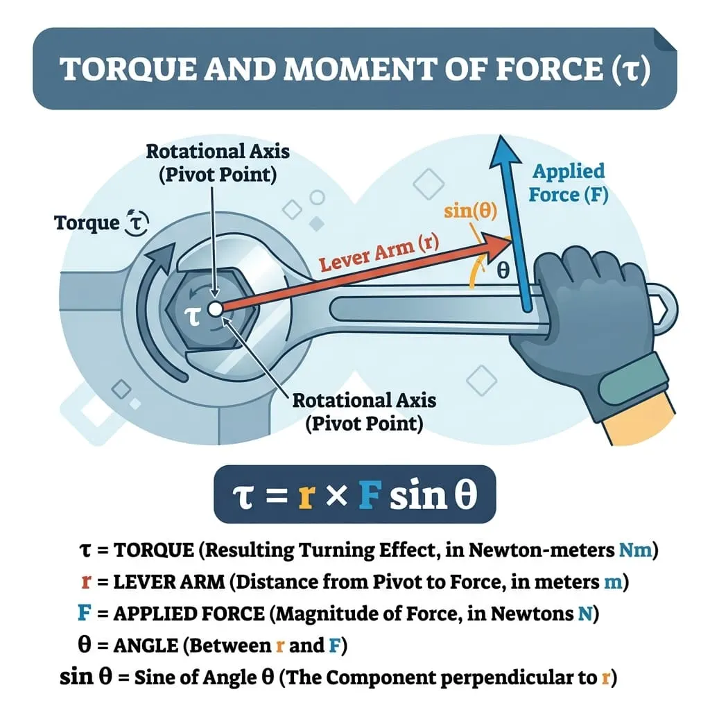
All these rotational phenomena are governed by a single physical quantity: Torque ($\tau$), also universally known across mechanical and structural engineering as the Moment of Force.
graph LR
    R["📏 Lever Arm (r)
Radial Distance Vector (m)"] -->|"Vector Cross Product (r × F)"| CROSS["🔄 Rotational Axis"]
    F["💥 Applied Force (F)
Force Vector in Newtons (N)"] -->|"Vector Cross Product"| CROSS
    TH["📐 Angle (θ)
Between Lever Arm & Force"] -->|"sin(θ) Perpendicular Factor"| CROSS
    CROSS -->|"Generates"| T["⚙️ Torque (τ)
τ = r · F · sin(θ) in N·m"]
While linear force causes objects to accelerate in a straight line (), Torque causes objects to rotate and accelerate angularly () around a pivot point or rotational axis.
Mastering torque enables engineers and technical professionals to:
- Properly specify and calibrate torque wrenches to avoid shearing fasteners or cracking engine cylinder heads.
- Design automotive transmission gearboxes, differential drive axles, and electric motor torque curves.
- Balance industrial crane counterweights and prevent catastrophic overturning moments.
- Optimize human biomechanics in orthopedics, physical therapy, and athletic strength training.
In this comprehensive guide, we dissect the mechanics of torque—from vector cross products and right-hand rule conventions to real-world industrial case studies and worked engineering calculations.
2. Definitions & Physical Meaning
2.1 The Simple Definition
In simple terms:
- Torque ($\tau$) is the "twisting" or "rotational" force that causes an object to spin.
- Torque depends on three factors:1. How hard you push: The magnitude of the force ().2. Where you push: The distance from the pivot point (the lever arm ).3. The angle of your push: The direction relative to the lever (). Pushing perpendicularly () generates maximum torque, while pushing directly toward the hinge () generates zero torque.
2.2 Formal Technical Definition
Formally, Torque is defined as the vector cross product of the position vector (originating at the rotational axis and terminating at the point of force application) and the applied force vector :
In scalar magnitude form:
Where:
- $\tau$ is the torque magnitude ().
- is the length of the position vector / lever arm ().
- is the magnitude of the applied force ().
- is the angle between the position vector and the force vector .
- is the moment arm (the perpendicular distance from the rotational axis to the line of action of the force).
2.3 The Right-Hand Rule & Direction of Torque
Torque is a pseudovector whose direction points along the axis of rotation perpendicular to the plane formed by and :
graph TD
    subgraph RHR ["🖐️ Right-Hand Rule for Rotational Torque"]
        Fingers["1. Point fingers along position vector r"]
        Curl["2. Curl fingers toward applied force vector F"]
        Thumb["3. Extended thumb points in direction of Torque vector τ"]
        Fingers --> Curl --> Thumb
end- Counter-Clockwise (CCW) Torque: Positive $(+)$ by standard Cartesian convention; torque vector points out of the page / screen ($\odot$).
- Clockwise (CW) Torque: Negative $(-)$ by standard Cartesian convention; torque vector points into the page / screen ($\otimes$).
3. Historical Milestones in Rotational Mechanics
timeline
    title Historical Evolution of Levers & Rotational Dynamics
    250 BCE : Archimedes discovers the Law of the Lever ('Give me a place to stand...')
    1000 CE : Ibn al-Haytham (Alhazen) analyzes static moments of physical balances
    1687 : Sir Isaac Newton establishes classical rotational equilibrium (Principia)
    1743 : Jean le Rond d'Alembert formulates dynamic torque and moment of inertia
    1775 : Leonhard Euler establishes Euler's Laws of Rotational Motion (τ = I·α)
1884 : William Thomson (Lord Kelvin) standardizes modern torque in electrical dynamos- Archimedes' Law of the Lever (c. 250 BCE): Archimedes formulated the first exact mathematical law of static moments: two masses balance on a lever if their distances from the fulcrum are inversely proportional to their weights ().
- Euler's Rotational Dynamics (1775): Leonhard Euler generalized Newton's second law for rotating rigid bodies, introducing the rotational analog of mass (Moment of Inertia ) and formulating the rotational equation of motion:
4. Master Formula Matrix & Unit Conversions
4.1 Master Formula Matrix
| Desired Variable | Given , () | Given , , | Given Moment of Inertia & | Given Rotational Power & | Given Rotational Work & |
|---|---|---|---|---|---|
| Torque ($\tau$) | |||||
| Applied Force () | — | ||||
| Lever Arm () | — | ||||
| Angular Accel. () | — |
4.2 Torque Unit Conversions
| Unit | Symbol | Equivalence in Newton-meters () | Domain of Application |
|---|---|---|---|
| Newton-meter (SI Base) | International scientific & automotive standard | ||
| Pound-foot (Imperial) | (or ) | US automotive engine ratings & heavy machinery | |
| Pound-inch | Precision electronics & aerospace fasteners | ||
| Kilogram-force meter | Legacy Japanese & European mechanical specs | ||
| Dyne-centimeter | Micro-electromechanical systems (MEMS) |
5. Rotational Power & Angular Work
In rotating machinery (such as electric vehicle motors, wind turbines, and industrial shafts), mechanical power is directly coupled to torque and rotational speed:
graph LR
    T["⚙️ Shaft Torque (τ)
in Newton-meters (N·m)"] --> MULT["✖️ Multiplied By"]
    W_ANG["🔄 Angular Speed (ω)
in Radians per second (rad/s)"] --> MULT
    MULT --> P["⚡ Mechanical Power (P)
P = τ · ω (Watts)"]
For rotational speed specified in standard Revolutions Per Minute ():
In Imperial Automotive Units:
6. Practical Real-World Calculation Examples
Example 1: Tightening Vehicle Wheel Lug Nuts with a Torque Wrench
- Scenario: A mechanic tightens automotive alloy wheel lug nuts to a specification of . The torque wrench has a handle length . The mechanic pushes perpendicularly ().
- Required Applied Force:
Example 2: Pulling on a Wrench at an Oblique Angle
- Scenario: A plumber pulls on a pipe wrench with a force , but cramped space forces them to pull at an acute angle of relative to the wrench handle.
- Resulting Torque:
(Notice pulling at loses nearly 36% of the available torque compared to pulling at ).
Example 3: Electric Vehicle Motor Power Calculation
- Scenario: A high-performance electric vehicle motor delivers a maximum continuous torque at an armature speed of .
- Step 1: Convert RPM to Radians/Second:
- Step 2: Compute Mechanical Power:
Example 4: Balancing a Playground Seesaw (Rotational Static Equilibrium)
- Scenario: A parent () sits on the left side of a seesaw at distance from the fulcrum. Their child has mass . Where must the child sit () to balance the seesaw in static equilibrium?
- Static Equilibrium Condition:
7. Real-World Engineering Case Studies
Case Study 1: Wind Turbine Gearbox Torque Overload Protection
- Background: A utility-scale offshore wind turbine features a massive diameter rotor rotating at a slow speed of under peak rated wind conditions ().
- Torque Calculation:- Angular velocity: .- Main Low-Speed Shaft Rotor Torque:
- Engineering Challenge: A sudden electrical grid disconnect cuts generator electrical counter-torque to zero in milliseconds. Without protection, the aerodynamic rotor torque would violently overspeed the blades and disintegrate the planetary gearbox.
- Solution: Multi-stage hydraulic aerodynamic blade pitch mechanisms instantly feather the blade attack angles (), dropping aerodynamic torque to zero within while high-capacity disk brakes clamp the intermediate high-speed shaft.
Case Study 2: Fastener Preload and the Torque-Tension Relationship
- Background: In aerospace and automotive engine assembly, bolts must be tightened with precise torque to create a clamping force (preload ) that prevents joint separation under cyclic vibration.
- The Short-Form Motosh Equation:
Where is the dimensionless torque coefficient (nut factor), is the nominal bolt diameter (), and is the target bolt preload tension ().
- Analysis:- For a high-strength Grade 10.9 cylinder head bolt ():- Target clamping preload: ().- Dry zinc-plated threads ():
- Lubricated threads with anti-seize paste ():
- Critical Engineering Insight: Applying to a lubricated bolt would produce of preload tension, exceeding the tensile yield strength of the steel and snapping the bolt in half!
8. Common Mistakes & How to Avoid Them
Mistake 1: Confusing Torque () and Mechanical Work ()
Although both share the dimensional units , Torque is a vector representing rotational effort and should always be expressed in . Work is a scalar representing energy transfer and is expressed in Joules ().
Mistake 2: Forgetting the Sine Component ()
Multiplying lever length directly by force () assumes the force is applied strictly at right angles (). If force is applied obliquely, you must multiply by .
Mistake 3: Over-tightening Lubricated Fasteners
Thread lubricants dramatically reduce thread friction (). Always reduce tightening torque by when using anti-seize or motor oil on bolt threads to prevent over-stretching the fastener.
9. Frequently Asked Questions (FAQ)
Q1: What is the difference between Torque and Force?
A: Force () causes linear translation in a straight line (). Torque ($\tau$) is the rotational analog of force that causes an object to rotate around an axis or pivot point ().
Q2: Why is torque maximized at a angle?
A: Because the trigonometric function reaches its absolute maximum value of $1.0$ when . At or , , meaning pushing or pulling parallel to the lever arm produces zero turning effect.
Q3: How do gear ratios multiply torque?
A: In a mechanical gear train with gear ratio , output torque scales directly with the gear ratio (), while output rotational speed decreases proportionally ().
Q4: What is a couple in physics?
A: A couple consists of two equal, opposite, and parallel forces whose lines of action do not coincide. A couple produces pure rotational torque without any net linear translatory force (, while ).
Q5: How is torque related to Angular Momentum?
A: Torque is the exact time derivative of angular momentum ():
If net external torque on a system is zero, total angular momentum is strictly conserved ().
Q6: Why do diesel engines produce higher torque at low RPM than gasoline engines?
A: Diesel engines feature higher compression ratios, longer piston stroke lengths (longer crankshaft lever arm ), and higher cylinder combustion peak pressures (), generating massive low-end torque.
Q7: Can torque be exerted without causing rotation?
A: Yes. In static structures (such as a cantilever bridge or a tight bolt that refuses to turn), applied torque is balanced by an equal and opposite reaction torque (), maintaining static equilibrium.
Q8: What is torsional deflection in rotating shafts?
A: When a shaft transmits torque $\tau$, it experiences elastic shear strain and twists through an angle of twist , where is shaft length, is polar moment of inertia, and is the material's shear modulus.
10. Summary & Key Takeaways
- Fundamental Formula: , where $\tau$ is in Newton-meters (), is the lever arm distance in meters (), and is in Newtons ().
- Perpendicular Effectiveness: Torque is maximized when force is perpendicular to the lever ().
- Rotational Dynamics: Net torque governs angular acceleration via Newton's Second Law for Rotation: .
- Rotational Power: Shaft power equals torque multiplied by angular speed: .
Additional Technical Guidelines & Measurement Standards
When conducting calculations for Torque & Rotational Force Calculator, maintaining quantitative precision and verifying input parameter boundaries is essential for reliable scenario evaluation. Always verify that raw numerical inputs are measured using standardized instrumentation, and double-check unit conversions prior to applying outputs in commercial, industrial, or academic projects.
For quantitative unit conversions and scientific calculations, always maintain at least four decimal places of precision during intermediate arithmetic stages before rounding final results. When preparing technical reports, laboratory documentation, or financial forecasts, cross-verify all output variables against established international measurement standards (such as SI, NIST, and ISO metric benchmarks) to guarantee consistent analytical rigor across all computational workflows.
MathsLover.com delivers this interactive solver 100% free of charge to foster global mathematical literacy, educational accessibility, and data-driven problem solving across scientific, technical, and academic communities worldwide.